Performance Strength
*C,Ku, multi band Available , meeting FCC and ITU-RS-580
requirements
*High quality aluminum reflector panels and galvanized steel
backup structure
*Self-aligning aluminum antenna reflector-no field alignment
*Galvanized steel elevation over azimuth pedestal
*Fixed foundation and Non penetrating foundation optional for
wider choice
*Survives 125 mph winds in any position and High wind
configuration optional
Description
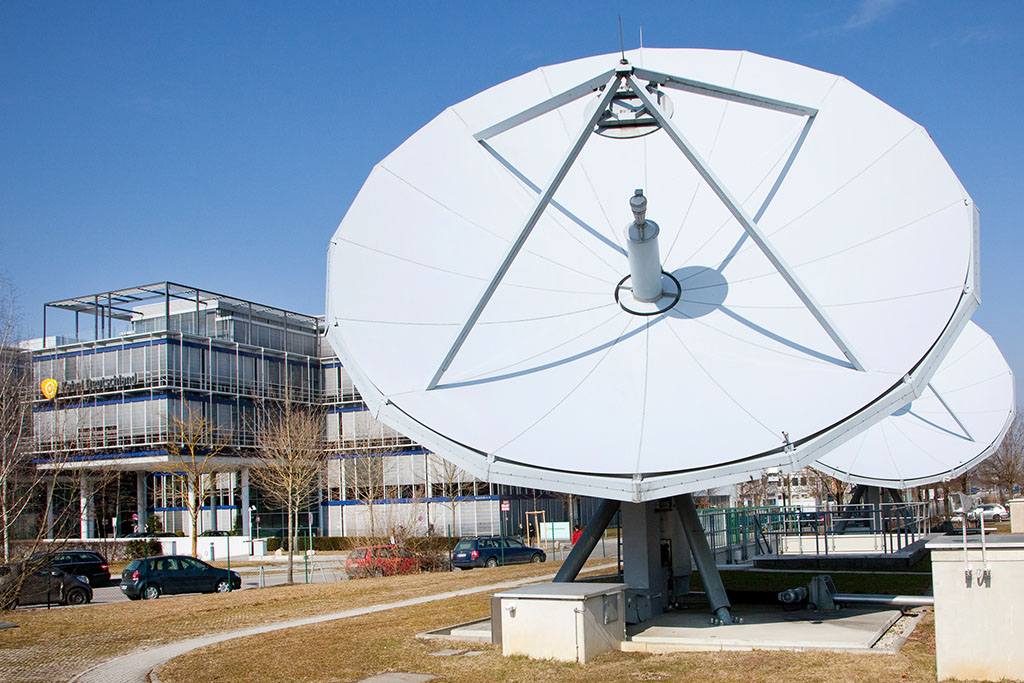
Starwin 7.3m antenna delivers exceptional high performance for
transmit/receive application in C ,Ku, ka, X band in Tx/Rx 2
ports, 4 ports or Rx 1 port with high gain ,low noise and low
microwave interference.
Starwin 7.3m antenna offers a fine reflector design with a
stretch formed double contoured panels, strong back struts and
hub fore ease of field alignment. The standard designed azimuth
over elevation pedestal provides a cost-effective solution for
ground or roof installation with high stiffness and stability ,
full orbital arc coverage and fine drive performance, and
ensures the pointing and tracking accuracy .
The electrical performance is compliant with FCC and ITU-RS-580
sidelobe specifications and Intelsat ,Eutelsat, INMARSAT,
ASIASAT,APT and CHINASAT, etc requirement.
Electrical, Mechanical, Environmental
Specification
|
Type
|
SW73C
|
SW73K
|
|
Operating
Frequency, GHz
|
C band
|
Ku band
|
|
Receive
|
Transmit
|
Receive
|
Transmit
|
|
3.4~4.2
|
5.85~6.725
|
10.95~12.75
|
13.75~14.5
|
|
Gain, Mid-band,
dBi
|
48
|
51.6
|
57.5
|
58.9
|
|
Polarization
|
Linear /circular
|
Linear
|
|
XPD(on Axis), dB
|
35
|
35
|
35
|
35
|
|
XPD across 1dB
Beam Width, dB
|
33
|
33
|
33
|
33
|
|
Axial Ratio
(Circular-Polarized)
|
2-Port Feed
4-Port Feed
|
1.30/1.06
|
1.09/1.06
|
|
|
|
VSWR
|
1.25
|
1.25
|
1.25
|
1.25
|
|
Antenna Noise
Temperature
2-port feed
10° Elevation
30° Elevation
50° Elevation
|
43°K
32°K
29°K
|
|
66°K
52°K
47°K
|
|
|
Typical
G/T(EL>10°,2-port)
|
29.3 dB/K
(30ºLNA)
|
|
36.1 dB/K
(70ºLNA)
|
|
|
-3 dB Beam
Width, Mid-band
|
0.72º
|
0.47º
|
0.23º
|
0.20º
|
|
Tx. Power
Capability, KW
|
|
5
|
|
2
|
|
Feed Interface
|
CPR—229G
|
CPR—137G
|
WR-75
|
WR-75
|
|
Feed Insertion
Loss, dB
|
0.2
|
0.2
|
0.25
|
0.2
|
|
Isolation, Tx to
Rx, dB
|
90
|
85
|
|
Side lobe
|
CCIR580-4
|
Key features
*Meets or exceeds CCIR 580 and INTELSAT Requirements
*High G/T, excellent pattern characteristic
*
Precision compression molded offset antenna
*CP/LP switchable feed
*
Hot dip zinc steel pedestal, hub & back struts
*Galvanized stainless steel fasteners
*
Foundation hardware kit provided
*
Package suitable for air, ocean land transportation
|
Mechanical
Specification
|
|
Antenna Diameter
|
7.3m
|
|
Antenna Type
|
Cass grain
|
|
Surface
Accuracy(RMS)
|
≤0.5mm
|
|
Antenna Pointing
Range
|
Azimuth
Elevation
Polarization
|
±85°, 0°-360°
continuous
optional
0°~90°(Continuous)
±90°(Continuous)
|
|
Drive Mode
|
Manual or
Motorized
|
|
Motor Drive
System
|
Azimuth Travel
Rate
Elevation Travel
Rate
Polarization
Travel Rate
|
0.11°/S(0.03°/S)
0.17°/S(0.04°/S)
1 ° / s
|
|
Antenna
reflector
Material
|
Aluminum Alloy
|
|
Finish of steel
parts
|
Hot dipped Zinc
|
|
Environmental
Specification
|
|
Operational Wind
|
72km/h gusting
to 97km/h
|
|
Survival Wind
|
216km/h
|
|
Temperature
|
-40°~+60°
|
|
Relative
Humidity
|
|
|
Solar Radiation
|
1135Kcal/h/m²
|
|
Seismic(Survival)
|
0.3g(H),
0.15g(V)
|
|
Ice Loading
|
13mm
Operational;
25mm Survival
|
Antenna Accessory
*Limit Switches
*Foundation hardware Kit
*Grounding Kits Cable –Mounting kits
*Cable mounting kits
*ODU Support Kits
*Factory Feed System Testing and Documentation
*Ocean /Air/land Transport Packing
Options
*
L, S, C, X, Ku and DBS-band feed configurations
*800MHz bandwidth is available
*Two or Four ports -Tx/Rx port in linear or circular polarized
feeds
*motorization kits
*Feed blower or deicing with automatic controls
*Lightning Rod Kits
*Non-penetrating mount
*
Antenna control & tracking system for step track, program track,
inclined orbit track
*
Integrated LNB or LNA systems
*HPAs, converters and M&C systems
*
Integrated LNB or LNA systems
*HPAs, converters and M&C systems
*
Turnkey installation & testing
Technical
specifications of DBS band antenna (7,3m)
|
PARAMETER
|
Specification data
|
Notes
|
|
ELECTRICAL
|
|
|
|
Tx frequency band (GHz)
|
17,300- 18,400
|
|
|
Rx frequency band (GHz)
|
10,700- 12,750
|
|
|
Tx gain (dBi)
|
>59,5
|
At mid-band
|
|
Rx gain (dBi)
|
>56,5
|
At mid-band
|
|
Feed assembly
|
Linear4 portfeed
|
|
|
Off axis emissions
|
ITU RS.524-5
|
|
|
G/T(dB/K)
|
>36
|
At 20° elevation with 65K LNB /
11,725GHz
|
|
Crosspol isolation
|
> 35 dB Tx & Rx
|
|
|
Sidelobes
|
Meets Intelsat, FCC 25.209, ITU
RS.580-5
|
|
|
Port to port isolation (min)
|
Tx to Rx 85dB RxtoTx70dB
|
|
|
Antenna noise temp
|
10° elevation 60K 20° elevation
50K 40° elevation 45K
|
|
|
Pattern beamwidth (deg)
|
Tx0,18 Rx 0,23
|
-3dB at mid-band
|
|
VSWR
|
Better than 1.3:1
|
|
|
Power handling per Tx port
|
IKWattsmin
|
|
|
Feed interface
|
Tx WR-62
|
|
|
Rx WR-75
|
|
|
|
|
|
MECHANICAL
|
|
|
|
Antenna type
|
Cassegrain with corrugated horn
|
|
|
Antenna travel
|
Elevation 0° - 90°
|
Continuous
|
|
Azimuth 180°
|
Max 2 segments
|
|
Polarization ±90°
|
|
|
Mount type
|
Elevation over azimuth
|
|
|
Antenna travel rate (min
|
Az 0,06° /sec
|
|
|
values)
|
El 0,03° /sec Pol 1,5°/sec
|
|
|
• Feed rainblower
• Aircraft warning lights
• Lighting kit
• Hub closeout kit
• Ladder & platform
• Dehydrator
• Tx couplers
|
Automatic
|
|
ENVIRONMENTAL
|
|
|
|
Operational temperature
|
-15° to +50° C
|
|
|
Survival temperature
|
-30° to +60° C
|
|
|
Relative humidity
|
0 to
|
|
|
Rain
|
10cm/h
|
|
|
Snow
|
5mm/h
|
|